
LED Profile Connectors: What to Check for Longer Lighting Runs
Plan longer LED profile runs by reviewing joint alignment, connector compatibility, diffuser lengths and assembly access before you order.
On This Page
For a longer line of light, plan the profile joints before placing your order. A connector may help align adjacent sections, but it must fit the selected profile and suit the installation. It is not automatically a structural support, an electrical connection or a guarantee of a seamless light line.
For the fitting steps, see installing LED strip lights with aluminum channel before you start the run.
Start With the Complete Run
Mark the intended line on a drawing and divide it into practical sections. Identify the mounting surface, direction changes, cable entry and areas where installers will need access. Consider the finished appearance at each joint and the length that can be handled and shipped to the project.
The joint locations should be reviewed together with the diffuser, end caps and LED strip. Two profiles can meet neatly while the cover or cable route still creates an assembly problem.
Separate Mechanical and Electrical Connections
A profile joiner connects or aligns physical sections. An LED strip connector is an electrical component. They solve different problems and should be listed separately in your specification.
Ask the relevant lighting supplier and qualified installer to review power feeds, connections and electrical requirements. Do not assume that a metal joiner is intended to carry current, or that a profile supplier’s component includes the electrical parts.
Check the Profile Interface
Confirm how the proposed joiner engages with the exact profile section. Review its position, installation direction and clearance around the LED strip and cover. A similar-looking section does not establish compatibility.
Some systems use connecting pieces or joining plates, while others use different arrangements. Availability and suitability depend on the product. Ask the supplier to identify the proposed parts and demonstrate their fit with the selected section. Do not treat a connector as universally interchangeable.
Plan Support and Access
Discuss mounting points with the installer rather than assuming that each joint can support the run. The required support depends on the assembly and its installation. Review how the profile is fixed, how a cover is removed and whether the joint remains accessible after surrounding finishes are complete.
For a suspended arrangement, have the responsible designer review the complete suspension system and applicable requirements. A profile alignment piece should not be described as a load-rated suspension component without the relevant documentation.
Review the Cover and Visible Joint
Decide whether profile and cover joints should line up or use another arrangement. Confirm the intended cover lengths and the access needed to insert or remove them. Where the appearance of a continuous light line matters, evaluate a representative assembly with the intended strip, diffuser and joints.
Ask what will be visible when the light is both on and off. A sample can help your team assess fit and appearance, but its result applies to the components and conditions tested.
Prepare Your Inquiry
Send a sketch of the run with section lengths, installation method, finish, quantities and destination. Identify corners, cable-entry points and access restrictions. List the profile, cover, end caps and any requested mechanical connection parts separately.
Ask the supplier to confirm the available connector options and their compatibility for your chosen assembly. If you are preparing a custom requirement, use the custom inquiry checklist or contact NIUYUAN with your drawing and questions.
Map the Run Before Selecting a Connection
Begin with the installation drawing rather than a connector catalog. Mark the start and end of each visible line and identify walls, panels, ceilings or furniture that support it. A continuous visual line may consist of several physical sections. Each joint is a place where the installer needs room to align and secure the assembly.
Show which sections are straight and where the layout changes direction. Record any transitions between different mounting surfaces. If a design includes corners, ask whether the project calls for a shaped connection, separately cut sections or another arrangement. The right answer depends on the section and the design; none of these methods should be assumed to be available for every profile.
Discuss the proposed joint layout with the installer and supplier before assigning final cut lengths. A drawing should identify the reference surfaces from which each length is measured. If the surrounding structure is not complete, mark the dimensions as preliminary and explain when they can be confirmed. This prevents an early estimate from being mistaken for an approved production dimension.
Understand What a Joining Part Does
Some joining parts are intended to assist with alignment. Others may be part of a broader assembly arrangement. Ask the supplier to describe the intended function of the proposed part and provide applicable installation information. Confirm whether additional fixing points are required near the connection.
Do not judge the connection by appearance alone. A piece that enters the end of a channel may interfere with the strip, cover or a nearby fixing screw. Check the available space in a representative assembly, including any features hidden inside the extrusion. If the connector occupies space that another component needs, resolve the arrangement before ordering.
Where a component is intended to carry an assembly load, obtain the documentation and have the responsible designer evaluate the complete installation. The ability to align two sections does not establish a load rating. This distinction is especially important when an assembly is suspended or installed where falling components would create a hazard.
Compare the Joint With the Surrounding Finish
The metal joint is only one part of the visible result. Examine the location of the joint in relation to nearby panels, walls and other architectural lines. Ask whether the meeting edges will remain visible, and identify the viewing distance and direction that matter to the project.
Review both the unlit assembly and the lit appearance. A joint that looks acceptable when switched off can be more noticeable once the lighting is operating. Conversely, an apparent difference seen at close range may be less important in the actual installation. Establish the acceptance question with the project team instead of promising an invisible seam.
Use the intended diffuser and strip when assessing the light line. The position of emitters, the cover and the joint can all influence appearance. A connector cannot by itself promise consistent brightness or eliminate visible points of light. If the result is critical, agree on the sample arrangement and the viewing conditions before comparing alternatives.
Plan the Diffuser Separately
List cover lengths independently from profile lengths. Ask how each cover is inserted and removed once the surrounding construction is complete. Some designs require access at the end; others may be fitted differently. Follow the instructions for the selected components rather than assuming one method applies to every profile.
Where there are multiple cover pieces, mark their proposed joints on the same drawing as the profile joints. Discuss whether coincident or offset joints best serve the design and assembly. A decision may depend on cover availability, the installation sequence and access. Confirm the proposed arrangement with the supplier and installer rather than making a universal rule.
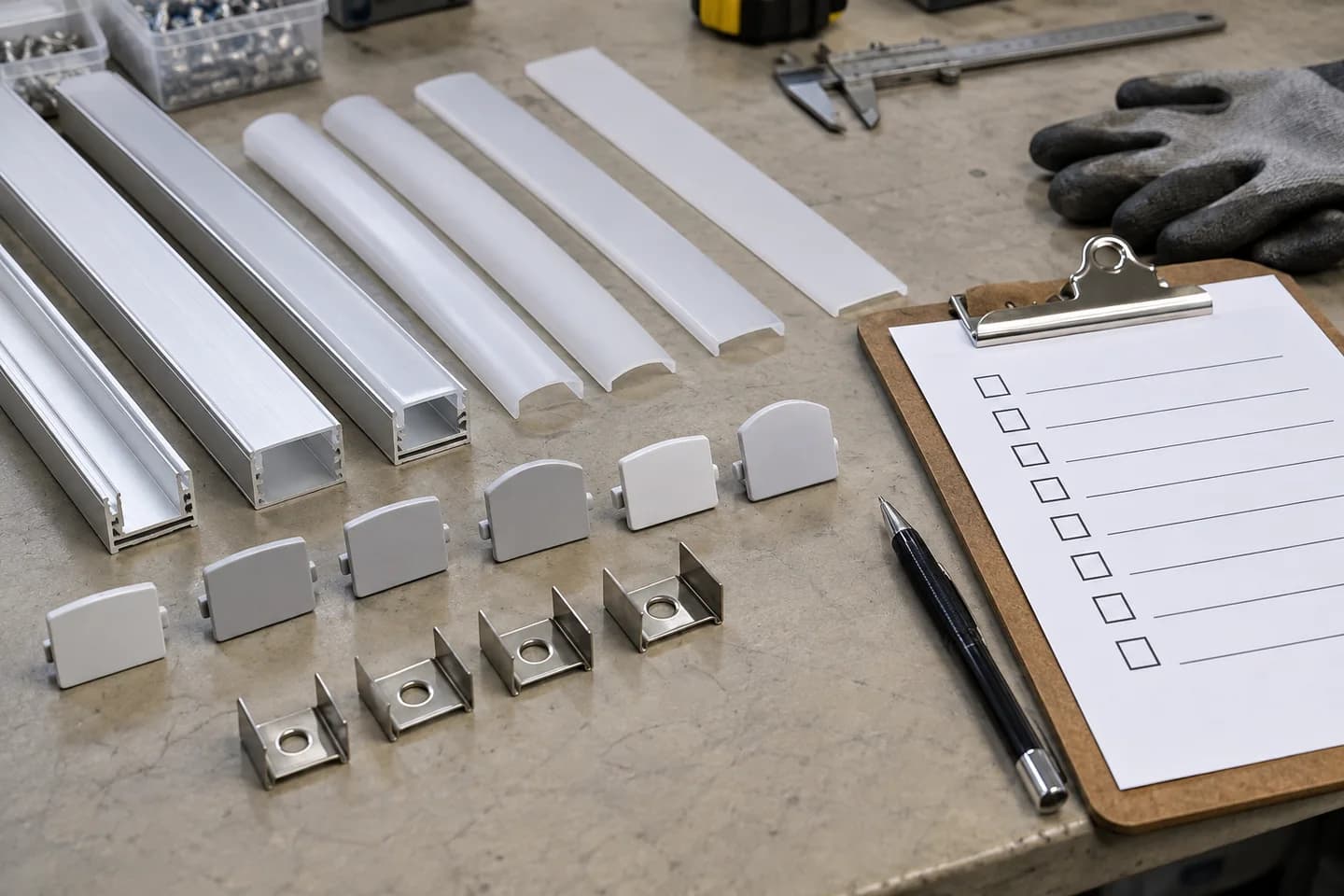
Include end caps and openings in the review. The cap, connector and cover need to fit the section and work with cable entry. If a cap is modified or a cable opening is required, describe the requirement before quotation. The order should identify which components are included and which are supplied by others.
Prepare a Representative Joint Sample
When fit or appearance is important, request a sample arrangement that represents the critical part of the project. Two short sections joined with their intended connection part may be useful for an initial interface review. If installation, cover insertion or access over a longer section is the main concern, discuss what sample length and setup are representative.
Keep a record of the section reference, connector, cover, finish and drawing revision included in the sample. Record the mounting method and the questions that the sample is intended to answer. An early fit sample does not automatically establish long-run behavior, structural suitability or the performance of a different lighting assembly.
If the project team changes the strip, profile, joint location or surrounding structure after the review, revisit the relevant acceptance questions. The purpose is not to repeat every check mechanically. It is to identify changes that could affect the fit, appearance or support that the earlier review addressed.
Make Quotations Comparable
Give each supplier the same piece schedule and connection requirements. Ask the quotation to identify the number of profiles, covers, mechanical joining parts, end caps and fixing components. Confirm whether the supplier has included processing, sample preparation, packing and any requested documentation.
If a proposed joint uses a connector supplied by another party, identify that responsibility. Ask each party what information it needs to review the interface. An unlisted accessory can change the apparent scope of a quotation, so compare complete assemblies and responsibilities instead of only the profile price.
Before approving the order, verify the proposed joint layout against the latest project drawing. Keep a list of unresolved items with an owner and a decision date. Once confirmed, use the same reference in the purchase order, sample approval and receiving inspection.
FAQ
Can one connector fit every LED profile?
No. The joining interface varies by profile. Confirm the proposed connection with the exact section and a representative assembly.
Will a connector eliminate dark spots at a joint?
Not necessarily. The visual result depends on the complete assembly, including the strip, diffuser and joint arrangement. Review a sample under the intended conditions.
Can I use a joiner instead of mounting supports?
Do not assume that. Have the installer or designer review the fixing and support requirements for the complete run.
Discuss Your Project
You can review profile accessories and send your requirements for review. Confirm the proposed supply scope, fit and order requirements with the team.

Share this guide
Tell us what you need
Send Your Project Requirements
Share your contact details and tell us which LED profiles you need.
Explore custom profile options