
How to Get Dotless LED Strip Lighting: COB, SMD and the Right Aluminum Profile
Learn how COB or SMD strips, diffuser choice and channel depth affect dotless LED lighting, with a practical sample approval and buying checklist.
On This Page
Quick Answer
A dotless light line depends on the complete assembly: the LED strip, spacing between emitters, distance to the diffuser, cover characteristics and viewing conditions. COB strips can make a continuous appearance easier to achieve, but they do not automatically approve the profile, joints, brightness or thermal performance. Select the parts together and approve a representative powered sample before placing a bulk order.
Introduction
An LED installation can appear continuous in a supplier photograph and still show bright points when fitted beneath a cabinet or reflected in a countertop. A shallow channel that looks discreet when switched off can also provide too little space for the proposed lighting arrangement.
For a project buyer, those problems usually appear late: after joinery dimensions are fixed, samples have been shown to a client, or components have already been ordered.
The solution is to treat “dotless” as a defined appearance requirement rather than a feature attached to one component. The cover, strip and aluminum section need to be evaluated as an assembly under the conditions in which customers will actually see them.
This guide explains the purchasing decisions behind a continuous-looking light line. It covers COB and SMD strip options, channel geometry, diffuser selection, sample testing and repeat-order controls. It also distinguishes optical approval from the electrical and thermal requirements that must still be checked separately.
01. Define What “Dotless” Means for the Project
A useful specification describes where the light is observed and what must look continuous.
There are several different viewing situations:
| Viewing situation | What the buyer should evaluate |
|---|---|
| Looking directly at the cover | Individual bright points and darker intervals |
| Looking at a glossy work surface | Reflections of emitters, joints and interruptions |
| Viewing a wall wash | Repeating bright and dark patterns on the surface |
| Seeing the lighting when switched off | Visible strip components and cover appearance |
| Looking along the channel | Differences at joints, ends and changes in direction |
A sample can pass one situation and fail another. For example, a concealed strip may produce an acceptable glow on a matte wall while remaining visible as separate points in a polished surface.
Write the intended observation positions into the brief. Identify normal viewing distances, ambient lighting and dimming conditions.
Avoid accepting “looks continuous” without explaining who will judge the sample and how. A short approval statement tied to a reference assembly is more useful than a broad marketing phrase.
02. COB vs SMD: What Changes for the Buyer?
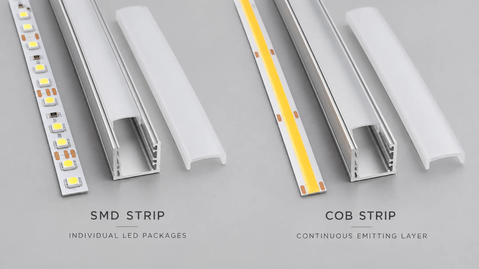
SMD LED Strips
In common strip-lighting terminology, SMD strips use separately packaged light emitters mounted along a circuit board. Their visible spacing is one factor in the appearance of the completed light line.
The package arrangement, emitting characteristics and circuit layout vary. Two strips described as SMD can therefore behave differently behind the same cover.
COB LED Strips
COB strip designs commonly place closely arranged LED chips on the flexible board beneath a phosphor layer. Environmental Lights describes this construction for its Continuous LED Strip Light range. The relevant purchasing advantage is the potential to reduce the appearance of individual points in a compact assembly. Environmental Lights: Continuous LED Strip Light
That does not mean all COB products are interchangeable. Check strip width, cut intervals, connection method, operating requirements and the available technical data.
Choose a Construction, Then Verify the Product
| Question | SMD candidate | COB candidate |
|---|---|---|
| Is the appearance acceptable? | Assess emitter spacing with the selected cover and gap | Assess the continuous emitting area, ends and joins |
| Does it fit? | Check board, packages, solder joints and connectors | Check board, emitting layer, solder joints and connectors |
| Can it be serviced? | Confirm access and replacement procedure | Confirm access and replacement procedure |
| Is thermal performance acceptable? | Validate the specified operating assembly | Validate the specified operating assembly |
Use the same acceptance process for both. “COB” is a construction description, not a complete performance specification.
03. LED Pitch and Optical Mixing Distance
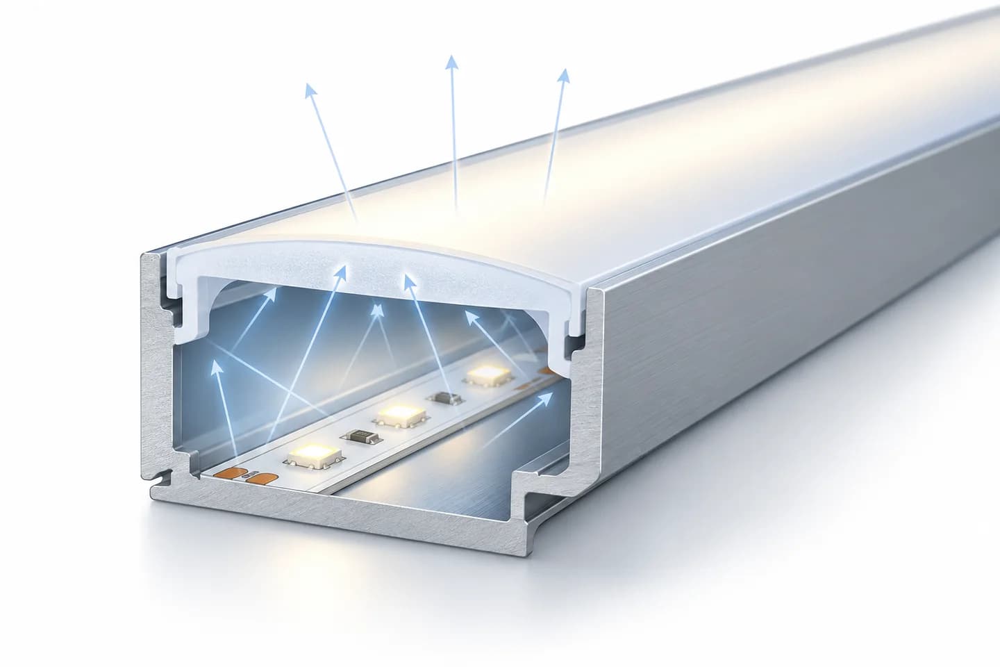
Understand the Distance Between Emitters
For an evenly spaced, single-row strip, nominal pitch can be estimated from the number of emitters per meter:
Nominal pitch in millimeters = 1,000 ÷ emitters per meter.
As an arithmetic example, 60 emitters per meter correspond to about 16.7 mm spacing, while 120 correspond to about 8.3 mm.
This calculation describes spacing. It does not establish the minimum channel depth or guarantee a dotless result. Real layouts can include grouped emitters, cut zones and nonuniform gaps.
Measure the Useful Optical Gap
The external height of an aluminum profile is not the same as the space available for light mixing.
The relevant gap is between the emitting surface and the appropriate diffuser surface. It is affected by the strip construction, mounting interface, internal profile geometry and cover shape.
Ask for a section drawing that makes those relationships clear. Do not compare two channels using external height alone.
Avoid Universal Ratios
A rule such as “the gap must equal the LED spacing” can be a starting hypothesis for a particular setup, but it should not become an approval criterion without validation.
A deeper channel may provide more room to evaluate different optical arrangements, but it must also fit the installation. The useful decision is whether the complete combination meets the appearance target within the available space.
04. Select the Diffuser as Part of the Assembly
A diffuser changes how the emitting surface is seen. It should be assessed with the actual strip rather than selected from an unlit color sample.
Compare these outcomes together:
- Visibility of individual emitters.
- Apparent brightness of the light line.
- Light reaching the intended surface.
- Appearance when switched off.
- Color appearance under the planned operating conditions.
- Cover fit and service access.
A cover that conceals points effectively may also change the amount and distribution of useful light. Do not assume that a smoother-looking cover automatically meets the illumination requirement.
Similarly, a dark-looking cover may support a particular unlit design while requiring a separate powered assessment. Color alone does not establish its optical performance.
NIUYUAN lists cover options for selected profiles and advises evaluating the intended strip-and-cover combination. Availability should be confirmed for the exact model, rather than assumed across the range. LED profile diffusers
Keep material selection separate from appearance selection. A PC or PMMA description does not, by itself, tell the buyer whether a cover will hide a particular strip.
05. Check the Space Needed for the Complete Installation
A strip can fit inside a channel while its connector does not. The same problem can occur when a cable exit or end cap occupies space that was not considered during selection.
Before approving a profile, review:
- Usable internal width for the strip.
- Space around solder joints and connectors.
- Clearance beneath the fitted diffuser.
- Cable entry and exit locations.
- Cover fitting and removal access.
- Joints, corners and end conditions.
- The mounting detail in the surrounding construction.
During installation preparation, use the relevant section drawing and component references. A photograph of the assembled channel may conceal the interfaces that determine whether it can actually be built and serviced.
For recessed or plaster-in work, coordinate the profile with the installer before finalizing the opening and finish. If a lighting decision is still open, record it before the surrounding construction removes access.
The existing surface-mounted versus recessed guide can help organize that installation discussion.
06. Build a Mock-Up That Can Answer the Purchasing Question
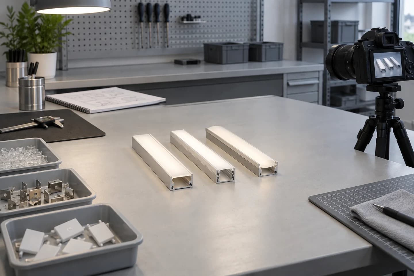
Use Representative Components
Assemble the intended strip, profile, cover and relevant end components. Include a connector, joint or corner when that detail is important to the project.
A sample that excludes the difficult detail can produce a misleading approval. Likewise, a supplier’s demonstration strip is not a substitute for the buyer’s intended product unless the substitution is understood.
Use appropriate electrical equipment and follow the strip manufacturer’s installation instructions.
Change One Variable at a Time
If the sample shows visible points, avoid replacing the strip, cover and profile simultaneously. That approach can produce a better result without revealing which change was responsible.
A practical comparison can begin with one profile and several cover candidates. Alternatively, compare two strip references in the same profile-and-cover assembly.
Record each combination. If more than one variable changes, identify the comparison as a different system rather than a controlled single-variable test.
Assess the Real Viewing Conditions
Check the light line from the intended viewing positions. Include nearby reflective surfaces where relevant.
Evaluate the expected operating settings and the dimmed settings important to the customer. Observe the sample directly; a camera can introduce its own exposure and capture effects.
Photographs are useful records when the camera position, exposure and lighting conditions are controlled. They should support the acceptance decision rather than replace direct assessment.
Agree on a Reproducible Acceptance Method
For a visual specification, identify the viewing arrangement, sample references and acceptable appearance. If the project requires a numerical uniformity criterion, define the metric, measurement positions, equipment and limit with a competent lighting professional.
Do not introduce an unexplained uniformity percentage or claim a standard test that has not been performed.
The approval record should be understandable to the supplier, buyer and installer without relying on the memory of the person who first saw the sample.
07. Troubleshoot the Pattern Before Replacing Parts
Different visual defects can point to different questions.
| Observation | What to investigate |
|---|---|
| Regular bright points along the whole run | Strip arrangement, cover characteristics and optical gap |
| A dark area at a connector | Connector position, local interruption and cover clearance |
| A dark line between profile sections | Strip continuity, joint design and end arrangement |
| Uneven brightness along a long run | Electrical design, permitted run length and supply arrangement |
| A smooth cover that is uncomfortable to view | Position, shielding, viewing angle and luminous surface |
| Good bench appearance but poor installed appearance | Changed viewing conditions, reflections or assembly details |
This table is a diagnostic starting point, not proof of a particular fault.
An optical change will not necessarily correct an electrical problem. For example, adding a more diffusing cover should not be the default response to a strip that becomes progressively dimmer along its length.
Refer electrical questions to the strip and driver documentation and the responsible installer. Use the profile discussion to resolve the mechanical and optical parts of the assembly.
08. Three Application Scenarios
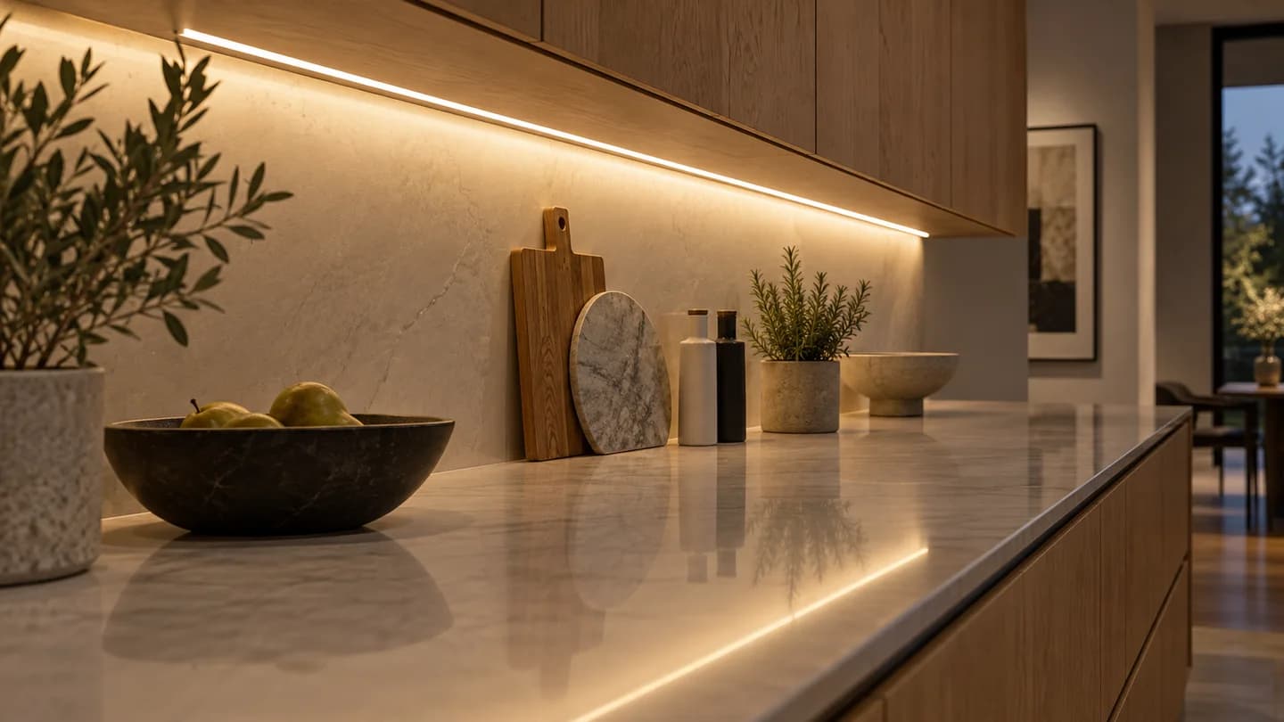
Under-Cabinet Lighting Above a Reflective Worktop
Consider a proposed kitchen or retail-counter installation. The strip is hidden behind a front edge, but the worktop reflects the emitting line.
A useful mock-up includes a representative surface and the planned mounting setback. Compare the reflected result from normal standing and seated positions.
The decision may involve strip construction, cover choice or mounting position. Approving only a photograph of the cover face would leave the most relevant viewing condition unchecked.
This is an illustrative review scenario, not a report of a completed NIUYUAN installation.
Retail Shelving
For shelving, assess both the light line and the products being illuminated. The most visually concealed strip is not automatically the best arrangement for merchandise visibility.
Include shelf depth, product position and surrounding illumination in the review. Ask the fixture designer to confirm that the selected arrangement meets the intended display objective.
Plaster-In Linear Details
For a plaster-in detail, review access before the surrounding finish is completed. The approved assembly should explain how the strip, connections and cover are installed and serviced.
The final appearance also depends on the continuity of joints and the quality of the surrounding work. A dotless bench sample cannot approve those construction details by itself.
09. Keep Optical Approval Separate from Thermal Approval
A continuous-looking light line does not demonstrate acceptable operating temperatures.
The selected strip still needs to operate within its documented limits in the actual installation. The channel, mounting interface, surrounding materials and operating conditions belong in that assessment.
Do not assume that a COB strip runs cool because its light appears continuous. Likewise, a channel chosen for optical depth should not automatically be described as an approved heat sink.
When arranging factory testing, distinguish the optical acceptance record from the electrical and thermal checks. This makes it clear which performance questions have been answered and which remain open.
For the thermal review, see LED strip heat management and aluminum channel selection.
10. Freeze the Combination Before Bulk Purchasing
Once the sample is accepted, record the complete combination: strip reference, profile reference, cover reference, fitting components, dimensions and relevant operating settings.
Keep that record with the approved sample and the purchase order. If a supplier proposes a substitution, identify whether it affects appearance, fit, service access or operating conditions.
For shipment inspection, verify that the supplied profile and cover references match the order. Check that similar components have not been mixed and that visible surfaces and fitting edges are protected.
During receiving, use the agreed inspection plan rather than assuming every carton requires the same checks. Where powered sample checks are included, use the same controlled setup that supported approval.
If the strip is supplied separately, coordinate its revision with the channel order. An unchanged aluminum profile does not make a changed strip-and-cover combination automatically equivalent.
NIUYUAN’s bulk purchasing checklist provides a broader framework for specification, inspection and packaging discussions.
FAQ
Does a COB Strip Eliminate the Need for an Aluminum Profile?
No universal rule applies. A COB strip may simplify the visual appearance, while the profile can still provide the intended mounting geometry, component arrangement and service detail. Thermal and environmental requirements must be assessed separately.
Will a Deeper Channel Always Remove LED Dots?
No. External depth does not define the optical gap, and the result also depends on the strip and cover. Use depth as a design variable to evaluate, not as an automatic guarantee.
Can a High-Density SMD Strip Look Dotless?
It can be a suitable candidate, but approval depends on the actual assembly and viewing conditions. Specify the strip reference and evaluate it with the proposed cover and profile.
Why Do I See Dots in a Countertop Reflection?
The reflection can reveal the emitting pattern even when the strip is hidden from direct view. Include the real surface finish and viewing position in the mock-up, then review the strip, cover and mounting arrangement.
Is a Phone Photograph Enough to Approve the Sample?
It is useful documentation, but it should not be the only basis for approval. Exposure, viewing angle and the display used to view the photograph can affect the impression. Keep the physical reference and agreed assessment conditions.
Does Dotless Mean Glare-Free?
No. Continuity and visual comfort are different requirements. Review the brightness and position of the visible surface as well as whether individual emitters can be distinguished.
What Information Helps a Supplier Review the Channel?
Provide the strip datasheet, usable installation space, profile reference if available, desired cover appearance and viewing conditions. Include the run arrangement and any connector or access constraints.
Conclusion
Dotless LED strip lighting is an assembly outcome. The most dependable purchasing process connects the strip, optical gap, diffuser, installation detail and viewing conditions to one approved reference.
Define the appearance you need, test the difficult details, and preserve the accepted combination through production and repeat orders.

Share this guide
Tell us what you need
Send Your Project Requirements
Share your contact details and tell us which LED profiles you need.
Explore custom profile options