
LED Strip Heat Management: How to Specify the Right Aluminum Channel
Specify aluminum LED channels using strip requirements, mounting interfaces and thermal testing. Learn why watts per meter alone cannot approve a profile.
On This Page
Quick Answer
An aluminum channel can provide a path for heat to move away from an LED strip, but its suitability depends on the strip, mounting interface, profile geometry and installed environment. There is no universal watts-per-meter rating for every aluminum profile. Start with the LED manufacturer’s requirements, then verify the complete assembly at the permitted operating conditions and the specified temperature measurement points.
For a broader selection view, see choosing the best LED aluminum channel before you shortlist profiles.
Introduction
“Will this channel handle my LED strip?” is a practical purchasing question. Unfortunately, it is often answered with an isolated power figure, a photograph of a substantial-looking extrusion or a statement that aluminum is a good heat conductor.
Those details do not establish the temperature of the installed LED assembly.
The same strip and channel can operate differently on an open test bench, inside a closed cabinet or within a recessed architectural detail. A change in the mounting interface can also affect how effectively heat reaches the metal.
For lighting brands, distributors and project buyers, the objective is to define a combination that meets the relevant component requirements under its intended conditions. That requires a useful technical brief, a representative sample and a test record that explains what was actually checked.
This guide focuses on the profile-related decisions that belong in that process. It explains the limits of watts-per-meter comparisons, the thermal path, practical testing requirements and the information to include when requesting a quotation.
01. Do All LED Strips Need an Aluminum Heat Sink?
No single answer applies to every strip.
Some products are designed to operate without an additional heat sink under their specified conditions. Waveform Lighting, for example, states that additional heatsinking is not required for its LED flex strips, while also providing operating conditions. That statement applies to its products; it should not be extended to an unidentified strip from another supplier. Waveform Lighting LED strip support
Other products or operating arrangements may require additional thermal management. The starting point is the documentation for the actual strip or light engine.
Ask the LED supplier:
- Is a heat sink or mounting surface required?
- Which operating conditions apply?
- Where should temperature be measured?
- What is the allowable value at that point?
- Are there restrictions on run length or enclosure?
- Which mounting interface is recommended?
A profile may still be useful for mounting, protection and appearance when a strip does not require it for cooling. Keep those reasons separate so the purchase specification explains the job each component must perform.
02. Follow the Complete Thermal Path
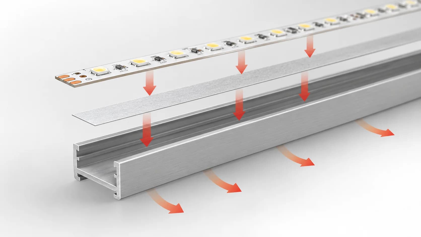
Heat must travel through a series of interfaces before it can reach the surrounding environment.
Depending on the product construction, the path can include the LED package, circuit board, mounting interface, aluminum profile and the transfer from the profile to its surroundings.
Lumileds describes overall thermal performance as a function of operating conditions and the resistance along the thermal path. A favorable heat sink cannot remove the need to understand the other interfaces. Lumileds: Practical Heat Sink Design for Illumination
The Interface Is Part of the Design
Review how the strip contacts the profile. Use the LED and adhesive suppliers’ recommendations for the intended assembly.
A component may appear to be securely mounted while still having an unsuitable contact arrangement. Check for contamination, unintended layers, local lifting and any interference that prevents the strip from sitting as intended.
Do not substitute an arbitrary foam tape or adhesive solely because it holds the strip in place. Mechanical attachment and thermal suitability are related purchasing questions, but they are not identical.
Exposed Geometry Matters
Ask which parts of the profile remain exposed after installation. A section mounted in open air should not automatically be treated as equivalent to the same section surrounded by construction materials.
Review the installed arrangement, including covers, supports and nearby components, before using a sample result to approve the project.
03. Use Watts per Meter as an Input, Not an Approval
A strip’s electrical power per unit length is useful for describing the load. It does not, by itself, determine the operating temperature.
As a planning example, a five-meter strip labeled 14.4 W/m has a nominal electrical input of:
5 m × 14.4 W/m = 72 W.
Compare W/m and W/ft
Some strip datasheets use watts per foot (W/ft) instead of watts per meter (W/m). Both express electrical power per unit length. To convert W/m to W/ft, multiply by 0.3048; to convert W/ft to W/m, divide by 0.3048. One international foot equals exactly 0.3048 meters. NIST: U.S. Survey Foot
For the illustrative 14.4 W/m strip above, the equivalent is about 4.39 W/ft. A total run figure describes the calculated electrical input for the stated length and rating conditions. Check the strip datasheet for its rating basis and operating conditions; a measurement can differ under another feed arrangement or setting.
That arithmetic does not select the driver, establish a profile rating or predict LED temperature. Actual operating conditions and measured power still need to be considered.
Also distinguish electrical input from the heat generated within the relevant part of the system. Light leaves the LED assembly as optical energy, while other losses occur in the strip, connections and power supply.
When comparing proposed assemblies, record the strip reference, operating voltage, permitted control setting and measured electrical conditions. For products with several channels, use the operating combinations allowed by the manufacturer rather than assuming that every channel can always be driven at its maximum simultaneously.
Two strips with the same nominal W/m figure should therefore remain separate candidates until their documentation and assembly requirements have been reviewed.
04. Why Channel Size Alone Cannot Establish a Rating
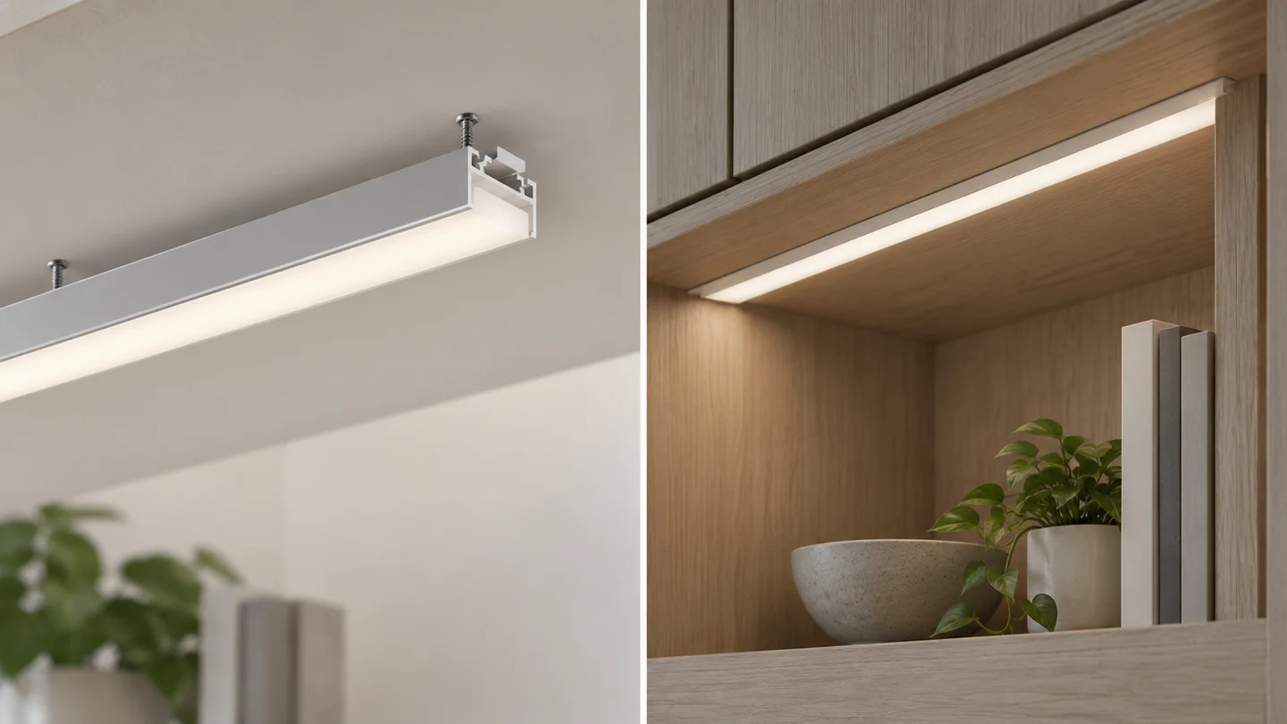
A wider or heavier section can offer useful design options, but the external dimensions do not tell the whole story.
Compare section drawings in the surface-mounted LED profile range, then evaluate the selected model in its intended mounting arrangement.
Consider the following specification variables:
| Variable | Purchasing question |
|---|---|
| Mounting surface | Does the strip sit against the intended surface throughout the run? |
| Internal width | Is there space for the board, connections and required clearances? |
| Profile geometry | Which surfaces are available in the installed arrangement? |
| Mounting orientation | Does the sample represent the actual product application? |
| Surrounding construction | Is the channel open, enclosed, recessed or otherwise constrained? |
| Cover and accessories | Were the intended parts fitted during evaluation? |
| Ambient conditions | Do the test conditions represent the proposed operating environment? |
Extra material can change the warm-up behavior, but a slower temperature rise is not the same as an acceptable final operating temperature.
If a supplier provides a watts-per-meter recommendation, ask for its basis. Identify the tested strip, interface, profile length, orientation, surrounding environment and acceptance limit.
Without those details, the number is difficult to transfer to a different project.
05. Know Which Temperature the Specification Refers To
Ambient, Reference-Point and Junction Temperatures
Ambient temperature describes the relevant surroundings. A manufacturer-defined reference temperature is measured at a particular point on the product. Junction temperature refers to the LED’s internal semiconductor junction.
These values are related, but they are not interchangeable.
Lumileds distinguishes thermal resistance values associated with different reference locations, illustrating why the chosen measurement point matters. Use the method and definitions supplied for the actual LED product. Lumileds: Measuring Thermal Resistance
Do Not Substitute a Convenient Surface
A measurement on the outside of the aluminum profile is not automatically the specified strip reference temperature. It is useful only for the question and method it represents.
Waveform’s CENTRIC DAYLIGHT datasheet, for example, defines its own reference point and thermal conditions. The lesson for a buyer is to obtain the equivalent information for the chosen strip, not to copy another product’s limits. Example manufacturer datasheet
Ask the supplier to identify the point clearly on a drawing or photograph. Keep that identification with the test record.
06. Prepare a Representative Thermal Evaluation
Define the Question Before the Test
Agree whether the evaluation concerns a new profile, a changed strip, a different mounting method or a different installation environment.
Write down the acceptance criteria before collecting readings. A test should answer a defined question rather than produce a photograph of a powered sample.
Build the Intended Assembly
Use the relevant strip, mounting interface, cover, end components and supports. Include the enclosure or surrounding detail where it materially affects the operating conditions.
Follow the electrical product instructions and use an appropriately qualified person for the powered evaluation.
Do not leave out a cover or nearby component simply because it makes the test easier to arrange. If a simplified sample is used for an initial comparison, identify the limitations and plan the final assembly check.
Record Conditions and Allow Stabilization
Record ambient conditions, orientation, electrical settings, run arrangement and the measurement method.
Monitor the specified points until the agreed stability criterion is met. A fixed photograph taken shortly after switch-on cannot establish the final operating condition.
The responsible technical team should define the measurement locations and stability criterion for the product. There is no need to invent a universal test duration for every strip and installation.
Report Observations Clearly
A useful report connects each reading to a location and condition. It should also identify any deviation from the intended assembly.
Separate “measured under these conditions” from a broader claim about all installations. An agreed sample result can support a defined specification without becoming an unrestricted product guarantee.
07. Use Appropriate Measurement Methods
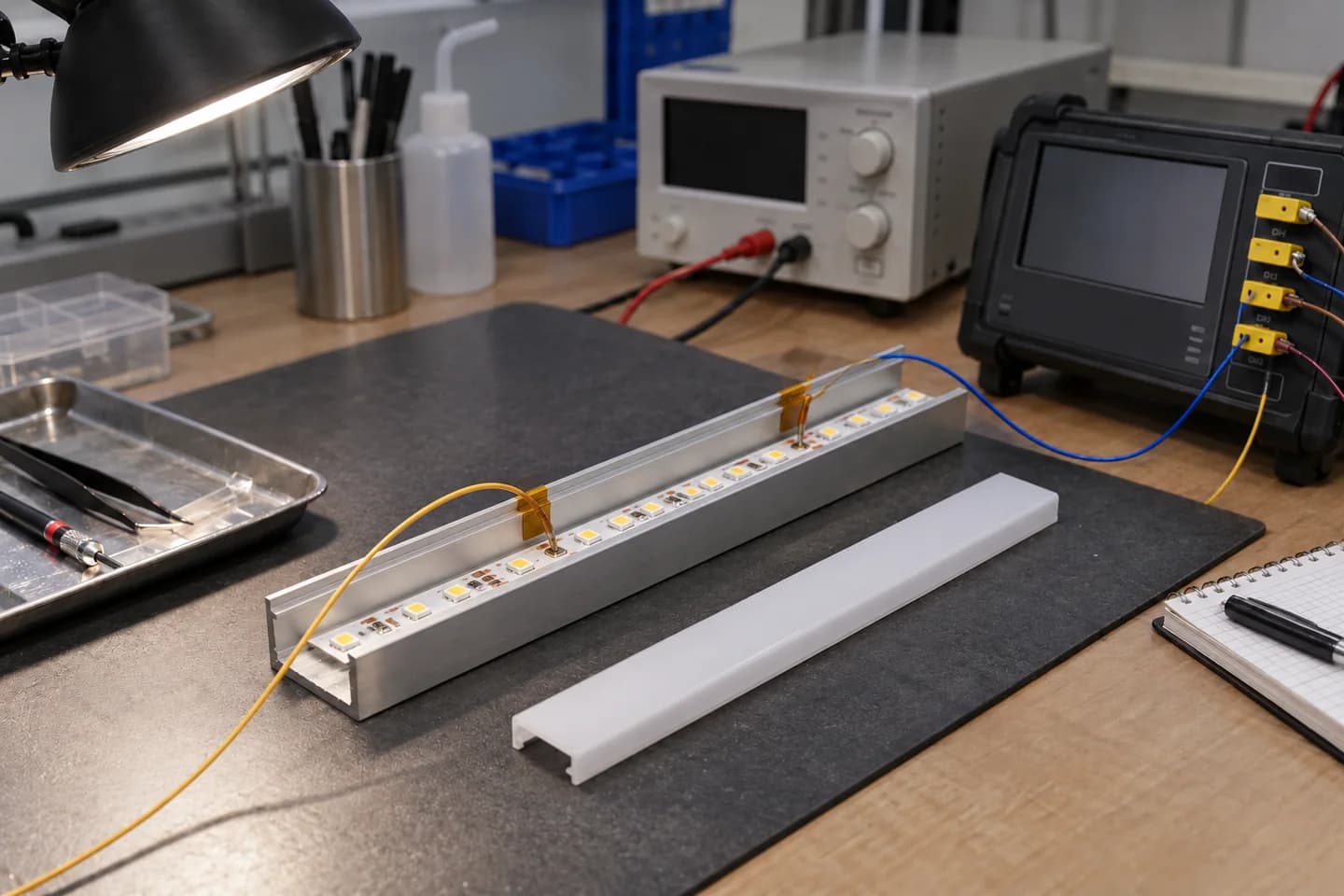
A thermal image is useful only when its measurement assumptions are understood.
Shiny or reflective metal surfaces can produce misleading infrared readings. Fluke explains that emissivity, reflections and measurement area affect infrared temperature measurement. Follow the instrument guidance and use a validated method for the surface being assessed. Fluke: Infrared Thermometer Measurement Guidance
A contact measurement may be appropriate where the product documentation specifies it, but the sensor must be placed and attached correctly. Avoid arranging the sensor in a way that changes the intended strip-to-profile contact or prevents the cover from fitting.
Also check what the instrument is actually measuring. A large measurement area can include surrounding surfaces and make a small target difficult to assess.
For a purchasing record, request the measurement point, method, instrument identification and relevant conditions. A colored image without those details should not be treated as a complete thermal approval.
Use measurements rather than touch to judge acceptance.
08. Diagnose an Unacceptable Result Systematically
If the measured result does not meet the requirement, work through the assembly instead of changing several components at once.
First, confirm the test setup. Verify that the strip, electrical settings, measurement point and ambient conditions match the intended specification.
Next, inspect the mounting interface. Look for unintended gaps, contamination, local lifting or a change in the specified attachment method.
Then review the installation arrangement. Check whether the profile’s exposed surfaces or surrounding conditions differ from those used in an earlier comparison.
Finally, review the component selection with the responsible suppliers. A different section, mounting arrangement or permitted operating setting may need evaluation.
Change one relevant variable at a time where practical, and record the effect. If the chosen solution changes the delivered light, include the optical requirement in the next review.
A thermal improvement should not silently create a different lighting product from the one the customer approved.
09. An Illustrative Cabinet-Lighting Review
Consider a buyer comparing an open-bench sample with a proposed installation inside enclosed joinery. The customer requirements include a discreet light line, a removable cover and a defined LED strip.
The bench sample is a useful starting point, but it does not represent every condition inside the cabinet.
A practical review would identify the finished mounting location, nearby materials, access and the relevant surrounding temperature. The technical team would then decide which conditions need to be reproduced in the sample.
If the installed arrangement changes, the earlier result should be reviewed rather than assumed to remain valid. The buyer should also confirm how the strip and cover can be serviced without changing the approved mounting method.
This is a proposed evaluation scenario, not a report of a completed NIUYUAN project or a measured temperature result.
The useful output is a documented assembly and its accepted conditions, supported by the appropriate product information.
10. Carry the Approved Specification into Production
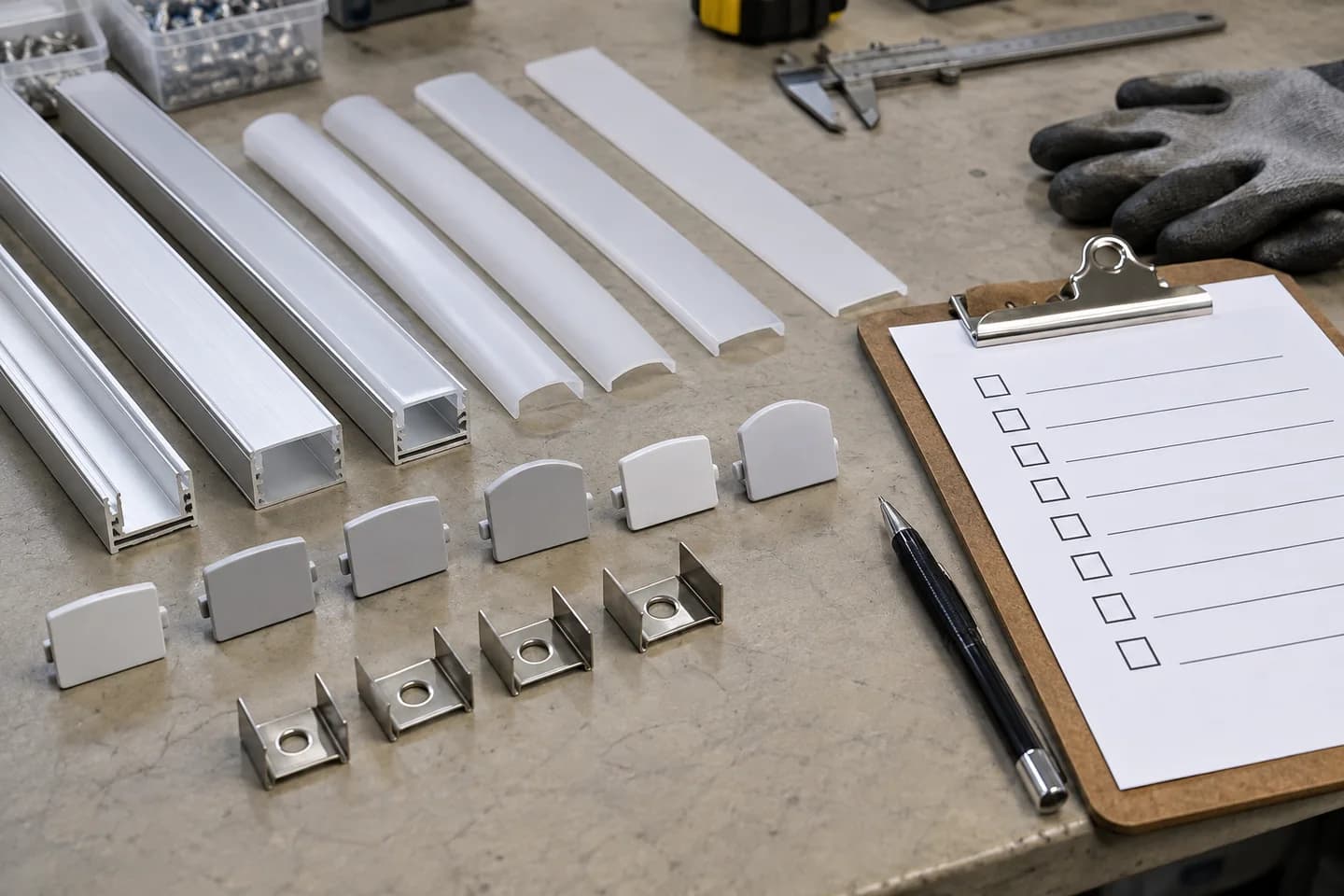
A successful sample can lose its value if production uses a different combination.
Keep the strip reference, profile drawing, material and finish requirements, mounting interface, cover and assembly instructions together.
Identify which changes require review. These may include a different strip, attachment material, profile section, component arrangement or operating condition.
For factory testing, distinguish basic product inspection from powered system evaluation. A profile supplier’s dimensional inspection does not automatically include testing of a lighting system assembled from separately supplied electrical components.
Where powered checks are part of the order, state their scope and the required records. Avoid describing an unspecified visual check as a thermal test.
For shipment inspection, verify the agreed product identity and the condition of the mounting surfaces and components. Damaged or mismatched parts should be resolved before they are incorporated into the intended assembly.
At receiving, maintain traceability to the approved specification so later questions can be investigated using the relevant product revision.
11. Prepare a Useful Profile Inquiry
The initial contact can be simple. A more detailed technical review should then collect:
- LED strip or light-engine reference and datasheet.
- Relevant electrical operating conditions.
- Required strip reference-temperature limits and measurement method.
- Profile model or section drawing.
- Intended mounting interface and installation arrangement.
- Cover, end-cap and connection requirements.
- Expected environment and service access.
- Lengths, quantities and destination.
- Required sample evaluation and inspection records.
If a value is unknown, identify the missing information rather than replacing it with an assumed rating.
Ask the quotation to distinguish the aluminum profile and accessories from LED strips, drivers and controllers. Also identify any testing, sample preparation or development work that needs separate agreement.
For broader order preparation, use the custom inquiry checklist and bulk purchasing guide.
FAQ
Is a Warm Aluminum Profile a Sign of Failure?
Not by itself. A surface temperature alone does not establish whether the LED product is within its specified limits. Evaluate the relevant measurement points under the intended operating conditions.
Can I Select a Channel Using Only the Strip’s W/m Rating?
No. Power per meter is useful load information, but the complete assembly and environment affect temperature. Obtain the product documentation and agree on the basis for selecting and evaluating the profile.
Is a Larger Profile Always Better?
Not automatically. The interface, exposed geometry and installed conditions still matter. Compare candidates using a representative assembly and the relevant acceptance criteria.
Do COB Strips Need Less Thermal Review Than SMD Strips?
No. COB and SMD describe aspects of construction. Use the thermal requirements of the actual product rather than treating either label as an exemption from evaluation.
Can an Infrared Photograph Approve the Assembly?
It can support a test record when the method is appropriate and documented. It should not replace the required reference-point measurements, operating conditions and acceptance criteria.
Does a Profile Inspection Report Prove LED Lifetime?
No. A dimensional inspection or sample temperature check has a defined scope. Lifetime claims require their own applicable evidence and should not be inferred from a general profile inspection.
Conclusion
An aluminum channel is one part of a lighting assembly’s thermal design. A reliable selection connects the LED requirements, mounting interface, profile geometry and installed conditions to a documented evaluation.
Use a watts-per-meter figure to describe the load, then use the appropriate product data and testing process to establish suitability.

Share this guide
Tell us what you need
Send Your Project Requirements
Share your contact details and tell us which LED profiles you need.
Explore custom profile options